Pages: 1 ... 8 9 [10] 11 12 ... 17   Go Down

Author Topic: DSLR testing sites like DXOmark and Imaging Resource use HMI and LEDs for color  (Read 56146 times)

digitaldog

  • Sr. Member
  • ****
  • Offline Offline
  • Posts: 20646
  • Andrew Rodney
    • http://www.digitaldog.net/
Logged
http://www.digitaldog.net/
Author "Color Management for Photographers".

digitaldog

  • Sr. Member
  • ****
  • Offline Offline
  • Posts: 20646
  • Andrew Rodney
    • http://www.digitaldog.net/

Nope, they sure aren't the same. People often think of D50 as the same as blackbody 5,000K but they aren't.
Yup, I wish I had a dollar for every post I've seen where people associate the the two as being the same. Which is why I strive to always place CCT somewhere around a numeric value that also has Kelvin associated with said value.
Logged
http://www.digitaldog.net/
Author "Color Management for Photographers".

Doug Gray

  • Sr. Member
  • ****
  • Offline Offline
  • Posts: 2197

Yup, I wish I had a dollar for every post I've seen where people associate the the two as being the same. Which is why I strive to always place CCT somewhere around a numeric value that also has Kelvin associated with said value.
So true. Seems to be a widespread belief.
Logged

Jim Kasson

  • Sr. Member
  • ****
  • Offline Offline
  • Posts: 2370
    • The Last Word

Yup, I wish I had a dollar for every post I've seen where people associate the the two as being the same. Which is why I strive to always place CCT somewhere around a numeric value that also has Kelvin associated with said value.

You go, Andrew! D50 doesn't even have a CCT of 5000 Kelvin; it's 5003, thanks to changes in the way that blackbody spectra are calculated since the D-illuminants were defined. It's a little difficult to credit in the computer age how the birth of the D-illuminants were affected by computational ease. And why should daylight act like a blackbody anyway?

Jim

digitaldog

  • Sr. Member
  • ****
  • Offline Offline
  • Posts: 20646
  • Andrew Rodney
    • http://www.digitaldog.net/

You go, Andrew! D50 doesn't even have a CCT of 5000 Kelvin; it's 5003, thanks to changes in the way that blackbody spectra are calculated since the D-illuminants were defined. It's a little difficult to credit in the computer age how the birth of the D-illuminants were affected by computational ease. And why should daylight act like a blackbody anyway?

Jim
Being mathematically challenged, can I assume there is more than one calculation and thus, that 5003 value could change?
Further when comparing our measurements to standard illuminants or such a conversion to CCT, useful to consider that D-illuminants were produced from many (622) measurements made around the planet, using differing spectroradiometers, and averaged to produce that definition used today. So the YMMV warning may apply?
Logged
http://www.digitaldog.net/
Author "Color Management for Photographers".

Jim Kasson

  • Sr. Member
  • ****
  • Offline Offline
  • Posts: 2370
    • The Last Word

Being mathematically challenged, can I assume there is more than one calculation and thus, that 5003 value could change?

It could change if the values of Planck's constants are revised again.

Take a look at the last section of this before the references:

https://en.wikipedia.org/wiki/Planckian_locus


Further when comparing our measurements to standard illuminants or such a conversion to CCT, useful to consider that D-illuminants were produced from many (622) measurements made around the planet, using differing spectroradiometers, and averaged to produce that definition used today. So the YMMV warning may apply?

Absolutely! If D50 is useful, it is useful as a normative standard for comparison, not as a measure of daylight at a particular time of day at a particular spot with particular weather conditions, or even as an average of some of the above.

Jim

Doug Gray

  • Sr. Member
  • ****
  • Offline Offline
  • Posts: 2197

You go, Andrew! D50 doesn't even have a CCT of 5000 Kelvin; it's 5003, thanks to changes in the way that blackbody spectra are calculated since the D-illuminants were defined. It's a little difficult to credit in the computer age how the birth of the D-illuminants were affected by computational ease. And why should daylight act like a blackbody anyway?

Jim

Worth noting that the dE difference between 5000K and 5003K is less than 0.1  Actually, D50 is pretty far away from a 5000K Planckian white. the visual differences between 5000K and 4750K/5250K are similar to the differences between D50 and 5003K (or 5000K). However, the D50 difference is along the (green) magenta axis while the 5000K->5250 is along the blue (yellow) axis.

Logged

Jim Kasson

  • Sr. Member
  • ****
  • Offline Offline
  • Posts: 2370
    • The Last Word

Worth noting that the dE difference between 5000K and 5003K is less than 0.1  Actually, D50 is pretty far away from a 5000K Planckian white. the visual differences between 5000K and 4750K/5250K are similar to the differences between D50 and 5003K (or 5000K). However, the D50 difference is along the (green) magenta axis while the 5000K->5250 is along the blue (yellow) axis.

Yes, that's been brought up before in this thread, but not, AFAIK, the CCT difference. Sure, it's academic, but it just points out one more way that D50 is not what some folks think it is.

Jim

WayneLarmon

  • Full Member
  • ***
  • Offline Offline
  • Posts: 162

That worked.  I'm pausing now to watch your sRGB Myths videos.  It covers a lot of what I am asking questions about.

I watched your video and then did a random walk looking at other spectrum analyzing programs.  During my random walk I hit on a (39 minute!) video done by a photographer that had been upset that various photo printing labs were apparently using canned profiles instead of having custom profiles done by a professional.  She had downloaded a bunch of profiles from the labs and ran them through ColorThink Pro's 3D grapher.  She also compared the gamut of one of her own images that had a lot of saturated colors and showed how the gnarly printer profiles wouldn't reproduce as many of the colors from her image as a printer that used a better (custom) profile would.  (Message: look for custom profiles.  That were done recently.)

I think I can use various ArgyllCMS utility programs to do 3D plots that are similar to Colorthink Pro 3D plots.  I had already done a bunch of 3D plots of profile gamuts.

While wondering how to better quantify color rendering under different illuminants, I decided to run the images I had previously took of a set under various LEDs (and under the real sun) that I previously posted through the ArgyllCMS programs.  This set


OK, here is where I'm guessing.  I loaded the set images into Photoshop from the raw files but this time I reconfigured ACR to load them as Lab.  I saved them as 8 bit TIFFs (as Lab) and made ArgyllCMS gamut files from them and made various 3D plots.

Here is a 2D image of the gamut of the set lit by Walmart bulbs against sRGB.


Here is the 3D plot.  I think this shows that some colors from this image poke out of sRGB a bit, correct?

Here is the gamut of the set lit with the Walmart bulb against the gamut of the set lit with real daylight


3D plot  There does seem to be some areas that real daylight covers that the Walmart bulb doesn't.  And some areas where the Walmart bulb apparently has more saturation than real daylight does.

I didn't make a 2D screen shot, but here is the set illuminated with the Walmart bulbs against the set illuminated with the Apurture Amaran AL-H198 LED panel.  These are closer but the Walmart bulb's gamut is still smaller than the Apurture panel's gamut is.

Here are all the 3D plots I did comparing the gamuts of the set lit with different illuminants.  Here are the 2D images of the set, ColorMeter spectrum plots, etc.

Now, am I testing anything meaningful here?   Am I getting any closer to quantifying color rendering ability?
« Last Edit: June 10, 2018, 08:54:58 pm by WayneLarmon »
Logged

WayneLarmon

  • Full Member
  • ***
  • Offline Offline
  • Posts: 162

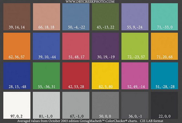
I did gamut plots again but with just the ColorChecker portion.  Also, I added in the CC chart in Lab format from Dry Creek Photo.  Here is the Dry Creek version (with labels of Lab values as read from Photoshop, when you open the Lab version from DCP, not the sRGB version I'm showing here.)


The gamut looks like this in 2D (done from the Lab version of the DCP image with no labels.)
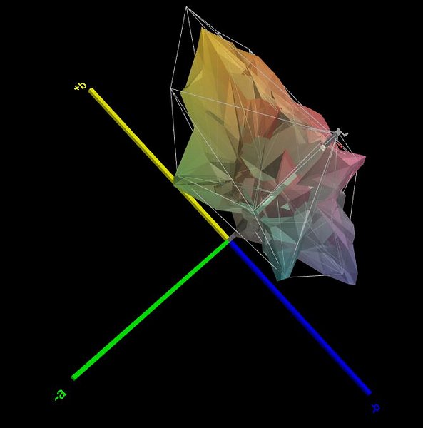
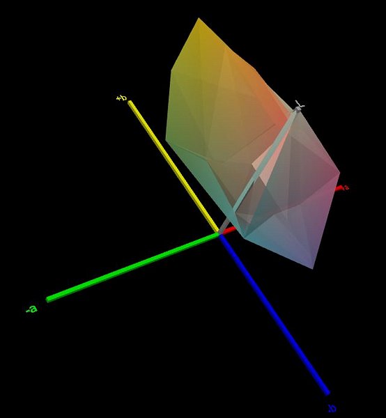
3D plot.  Smoother (DCP's is an average.  Or maybe was CGIed?)

Here is the CC portion of my set image shot in real daylight after I used Photoshop's Perspective Crop to crop out just the CC chart.


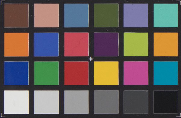
Differences in processing: I opened the images up in Lab mode in ACR but this time I switched the profile from "Adobe Color" to "Adobe Standard".  And white balanced on the 2nd gray chip (instead of on the WhiBal card.)  The Dry Creek Photo chip was 81,-1,0.  I adjusted exposure in ACR so this chip was 81,0,0 (The ColorCheck Passport card's bottom row isn't really neutral according to Robin Myers, which is why I originally used my WhiBal card.)

Here is the 2D plot of the gamut of my CC card shot in daylight.
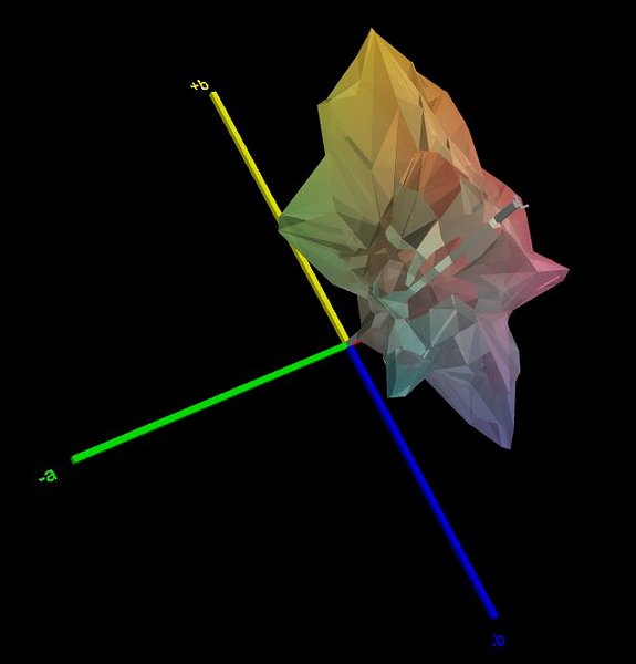
3D plot.

And here is a 2D plot of the gamut of my CC card shot in daylight against the gamut of the Dry Creek Photo CC card.

3D plot.

The gamut of the DCP card doesn't go as close to black as the gamuts of my CC card, presumably because the surround of the DCP card is gray while the surround of my ColorChecker Passport card is closer to black.

I don't know why the gamut of the DCP card is larger than my own CC card shots.  Possibly because of different raw converters?  Or because DCP used a different camera profile than Adobe Standard?  All of my CC card shots were processed the same (opened and saved in Lab, the using Adobe Standard profile.)  Or (after rereading the DCP page), maybe the DCP chart is synthetic and was created entirely in Photoshop; and wasn't shot from a camera at all.

Here is an updated page of my 3D gamut plots showing with all the illuminants I used before (Walmart, Cree, Aperture, real daylight) in different permutations.  With the DCP card mixed in.

When looking at the table sorted by Cubic Colorspace Units at the bottom of the above page I see that the gamut plots I did earlier of the entire sets are a lot larger than the gamut of just the CC card.  Maybe because the real world objects in my set are more saturated than the CC card?  Or maybe they are just different hues, so there are more samples?

Is any of this showing us anything about color rendering under different illuminants?  Or am I just making colorful Rorschach tests?
« Last Edit: June 11, 2018, 05:31:50 pm by WayneLarmon »
Logged

Doug Gray

  • Sr. Member
  • ****
  • Offline Offline
  • Posts: 2197

Is any of this showing us anything about color rendering under different illuminants?  Or am I just making colorful Rorschach tests?
Well, they are quite pretty!

When trying to analyze the quality of lighting and camera profiles it's best to use "scene referred" techniques with the exception of adjusting the white point to a common value. Most all image converters do "output referred" conversions which typically increase saturation and introduce an "S" tone curve to accommodate the large dynamic range most photographed scenes have. This makes them look better when printed.

Also, with scene referred processing one can compare Lab values and associated statistics.

However, there isn't a lot of good info on this as it's more a specialty of people that replicate artwork but you can find some here and by googling.
Logged

WayneLarmon

  • Full Member
  • ***
  • Offline Offline
  • Posts: 162

Well, they are quite pretty!

I was trying to demonstrate a model for a better color rendering metric.   Refer to my 3D plot of the gamut of my set illuminated by Walmart bulbs against the gamut of the set illuminated by real daylight. The 3D plot shows both decreased and increased saturation of all colors. (Increased saturation can be just as bad as decreased saturation.)  Plus or minus any deficiencies of my methodology (such as differing CCTs.)

This is an example of the kind of color rendering test results I'd like to see.  I'd like to see a 3D plot showing exactly how much the artificial illuminant diverges from real daylight (or real tungsten).  In addition to the very small list of single digit measurements (CRI, TLCI, etc.) that we now have.  A 2D spectral plot isn't much better.

My demonstration only attempted to show saturation.  It didn't cover hue shifts (that would require arrows.) 

I don't know if my test is realizable from just a spectral measurement of the illuminant.

Quote
When trying to analyze the quality of lighting and camera profiles it's best to use "scene referred" techniques with the exception of adjusting the white point to a common value. ...

This covers the entire pipeline.  This is important!  Thanks for the suggestions.  I'm already Googling. 

But I was restricting my demonstration to color rendering.  Photographers need better metrics so we can decide how high up the illuminant chain we need to go.   To cut down on lighting manufacturers gaming the system with color rendering tests that do not adequately describe actual color rendering.  Heck, just getting SPDs is difficult enough.

Before we get into Luther/Ives and the Sensitivity Metemerism Index (SMI) tarpit.

Wayne
Logged

Alexey.Danilchenko

  • Sr. Member
  • ****
  • Offline Offline
  • Posts: 257
    • Spectron

This is an example of the kind of color rendering test results I'd like to see.  I'd like to see a 3D plot showing exactly how much the artificial illuminant diverges from real daylight

Could you please define real daylight? This is quite a misnomer because daylight tend to differ and substantially depending on time of day, weather conditions etc.

A 2D spectral plot isn't much better.

SPD of a light source technically is all you need from a light source to model, evaluate and profile the rest (assuming you also have spectral responses of the sensor or sensor+lens combination).
Logged

WayneLarmon

  • Full Member
  • ***
  • Offline Offline
  • Posts: 162

Could you please define real daylight? This is quite a misnomer because daylight tend to differ and substantially depending on time of day, weather conditions etc.


Relative spectral power distribution of illuminant D and a black body of the same correlated color temperature (in red), normalized about 560 nm.
https://en.wikipedia.org/wiki/Standard_illuminant

Real daylight with the same CCT as the illuminant that is being tested.   

Or the D illuminant doppelgängers.  For my above demonstrations, substitute a D illuminant for the set (or whatever) being shot in real daylight (or real tungsten).  If that is more realizable then modeling lumpy real daylight.

Color rendering tests are for choosing artificial light sources.  As a photographer, can I get away with LED bulbs from a hardware store?  Or a LED panel from B&H?  Or do I need to get into fabricating Yuji components?  We need better color rendering tests.

Quote
SPD of a light source technically is all you need from a light source to model, evaluate and profile the rest (assuming you also have spectral responses of the sensor or sensor+lens combination).

So how do we do it?  The ArgyllCMS programs are powerful (and are portable--Win 10 tablets or netbooks are cheap as chips.)  I'm mathematically challenged but can slap together wrapper Perl scripts to call ArgyllCMS programs.  If I had guidance.
« Last Edit: June 12, 2018, 09:31:31 am by WayneLarmon »
Logged

Jim Kasson

  • Sr. Member
  • ****
  • Offline Offline
  • Posts: 2370
    • The Last Word


... We need better color rendering tests.

So how do we do it?  The ArgyllCMS programs are powerful (and are portable--Win 10 tablets or netbooks are cheap as chips.)  I'm mathematically challenged but can slap together wrapper Perl scripts to call ArgyllCMS programs.  If I had guidance.

In the early 90s, I wrote some programs to do this. More recently, Jack Hogan and I wrote Matlab code to optimize compromise matrices for specific cameras.

The process is not well defined. Some key decisions: What light spectrum or spectra? What set of reflectance spectra for the training set? What is the error function (avg? rms? Lab? Luv? Lab 2000?) Are some patches in the training set weighted more heavily than others? Is the test patch set different than the training set (it better be unless the training set is very large)? What do you do with a solution space that is polymodal (I have found the genetic algorithm inefficient and simulated annealing better)? Do you allow LUT-based conversions instead of or in addition to compromise matrices? If so, how do you constrain the LUTs? And finally, and practically, can you code all this up to run in a reasonable length of time, especially with training sets that are at least in the mid-hundreds?

I've decided that, for now, life's too short for me to pursue this any more. Jack took it further than I did, and maybe he's got some advice, but I don't think Jack extended the training set beyond the Macbeth CC, which is very small.

Jim

Alexey.Danilchenko

  • Sr. Member
  • ****
  • Offline Offline
  • Posts: 257
    • Spectron

Real daylight with the same CCT as the illuminant that is being tested.   

Or the D illuminant doppelgängers.  For my above demonstrations, substitute a D illuminant for the set (or whatever) being shot in real daylight (or real tungsten).  If that is more realizable then modeling lumpy real daylight.

So you were in fact referring to D type illuminants - anyone in particular that you are trying to match?
 
Color rendering tests are for choosing artificial light sources.  As a photographer, can I get away with LED bulbs from a hardware store?  Or a LED panel from B&H?  Or do I need to get into fabricating Yuji components?  We need better color rendering tests.

So how do we do it?  The ArgyllCMS programs are powerful (and are portable--Win 10 tablets or netbooks are cheap as chips.)  I'm mathematically challenged but can slap together wrapper Perl scripts to call ArgyllCMS programs.  If I had guidance.

Any good book which explains CIE colour model and calculations will do to start with to see how to obtain colour from spectral data (light, object, observer essentially). With cameras/sensors it is the same - observer is the camera in this case.

Logged

WayneLarmon

  • Full Member
  • ***
  • Offline Offline
  • Posts: 162

So you were in fact referring to D type illuminants - anyone in particular that you are trying to match?

Whichever one that has a CCT that is closest to the light being tested. 
 
Quote
Any good book which explains CIE colour model and calculations will do to start with to see how to obtain colour from spectral data (light, object, observer essentially).

I just reread chapter three of a good book and it tells how to do CRI.   I was looking for something more meaningful.  I'm not sure if IES TM-30-15 will be much of an improvement (after Graeme adds it to ColorMeter.)

I'll repeat that I am mathematically challenged so I can't even do CRI by myself from spectral data.  (I'm moving from ColorMeter to ArgyllCMS spotread so I can collect spectral data when I'm testing lights.  I need to configure my Win 10 tablet with ArgyllCMS first.) 

Quote
With cameras/sensors it is the same - observer is the camera in this case.

I believe that my above demonstrations show the difference in color rendering between the three illuminants I tested and real daylight at the time I made an image of the same set in real daylight.   If I am using the same scene, camera, camera settings, and raw conversion for all four images, doesn't that null out the camera and post processing? (For this particular test.)

And somewhat less ambitiously, plotting an image's gamut against standard color spaces shows if that particular scene will fit in a given color space (sRGB, etc.)  I think I got a correlation with the 2nd demonstration (just the ColorChecker card) where cyan pokes a bit out of sRGB.  Andrew's "sRGB Myths" video also shows cyan poking out of sRGB (he used ColorThink Pro to plot an image's gamut against a color space, compared to me using ArgyllCMS programs.)
« Last Edit: June 12, 2018, 05:11:17 pm by WayneLarmon »
Logged

Alexey.Danilchenko

  • Sr. Member
  • ****
  • Offline Offline
  • Posts: 257
    • Spectron


I just reread chapter three of a good book and it tells how to do CRI.   I was looking for something more meaningful.  I'm not sure if IES TM-30-15 will be much of an improvement (after Graeme adds it to ColorMeter.)

If you are looking to a single quantitative measure to describe the quality of light for photographic application then in my view you are wasting your time. A "usefulness" of a single measure will be as "good" as DxO camera marks which is total rubbish. To many variables to pack into one measure, quite difficult to place weights on those variables simply because those could be application specific. For instance for someone shooting paintings/art matching of specific paints will be more important that any natural colours (skintones, sky etc).

Jim above fairly thoroughly described what is involved. I personally would build profiles with that light (lighting something like CC SG target or custom target if needed) and evaluate their accuracy against variety of shots and (if that is your goal) against the same profile built with daylight (though this is rather tricky).

In the light source I personally would look at SPD to see if the visible range is well covered, then for the smoothness. Most of the LEDs fail in this respect  since they have no coverage below 420nm and the large spike to start with (which means for extended range you need to add more different LEDs to the mixture). Yuji so far was the only one I know that gave fairly broad coverage including <420nm (it starts with 380nm). The shape of their SPD loosely follows the D illuminant (no exact fit of course) which is what interested me personally so I replaced my Xenon lighting with them. No regrets so far. Any alternative that I know of is to assemble panel of LEDs covering various wavelength and in total covering the whole visible range - then controlling their intensities to vary the shape of SPD. But that gets progressively harder with the number of LEDs involved (different current requirements, different brightness ranges etc).

I do plan to do the target and profile testing with Yuji D50 LEDs (properly lit target etc) but first I need to build those panels (not the point light source I have already done).

« Last Edit: June 13, 2018, 03:38:28 am by Alexey.Danilchenko »
Logged

WayneLarmon

  • Full Member
  • ***
  • Offline Offline
  • Posts: 162

If you are looking to a single quantitative measure to describe the quality of light

My experiments were designed to find a better CRI.  This is how a human standard observer perceives color matches.   I really liked the 3D plots from my demonstration that showed what colors in the artificial light had less saturation and what colors had more saturation.  I thought that this is more meaningful than the standard palette of 8-15 colors that various flavors of CRI (and variants) use.

Quote
for photographic application

I wasn't attempting that in my test.  As I pointed out the camera and processing were nulled out.

I assumed that everybody here would have realized what I was attempting to do (and what I was not attempting to do) so I didn't explicitly explain this.  I expected that people would point out deficiencies in my methodology and would suggest improvements.   I expected that people would ask for the parameters I passed to iccgamut, tiffgamut and viewgam.

And then, ideally, a way to skip shooting in real daylight.  I understand that this is a lot more difficult than passing parameters to the existing ArgyllCMS programs.   But skipping shooting in daylight isn't mandatory for this test.  Possibly the accuracy of shooting the object in real daylight could be improved by making a table of different CCTs of daylight at different times of day, in shade and in direct sunlight.  I haven't done this yet.

Baby steps first.  First an improved standard observer metric.  Before introducing the complexities of Luther/Ives and SMI.  (I'm not sure how TLCI handles this.)

Quote
Jim above fairly thoroughly described what is involved.

I read Jim's paper last night.  Even though I didn't understand it, I was impressed with the complexity that goes on behind the scenes in image processing programs.

I'm not underestimating complexity.  I'm trying to harness complexity that has already been solved.  Such as with the ArgyllCMS programs which are really powerful.  I was hoping that others would suggest other ways they can be used. 

Preferably augmented with additional algorithms to reprocess spectral data.  I can do algorithms.  It is math that I have a problem with.
Logged

Doug Gray

  • Sr. Member
  • ****
  • Offline Offline
  • Posts: 2197

Whichever one that has a CCT that is closest to the light being tested. 

The problem is that getting the closest to some CCT ignores the green/magenta error, which is unlimited.


My demonstration only attempted to show saturation.  It didn't cover hue shifts (that would require arrows.) 

And those (hue shifts) are what human vision is most sensitive to as saturation increases. In fact, generally human vision becomes less sensitive to changes in saturation as the saturation increases while hue shifts remain more perceivable. This is a principal reason I find 3D gamut images not very useful. It's more useful for showing saturation than hue shifts.

Logged
Pages: 1 ... 8 9 [10] 11 12 ... 17   Go Up